CForth HLow Power Hardware DIY Construction Manual
PCB layouts are described for:
STM32G431KB, STM32F042F6/K6 (without USB interface and low system clock frequency = 921.6 kHz)
furthermore: STM32L031K6 (system clock frequency = 1048 kHz)
and: STM32F030K6 (system clock frequency = 921.6 kHz, only 4kB SRAM) is described.
Because it is complicated to etch PCBs without appropriate tools, Veroboard wiring compatible layouts are developed, but can be etched as 1 layer PCB, too.
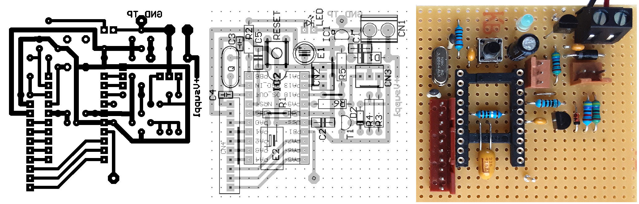
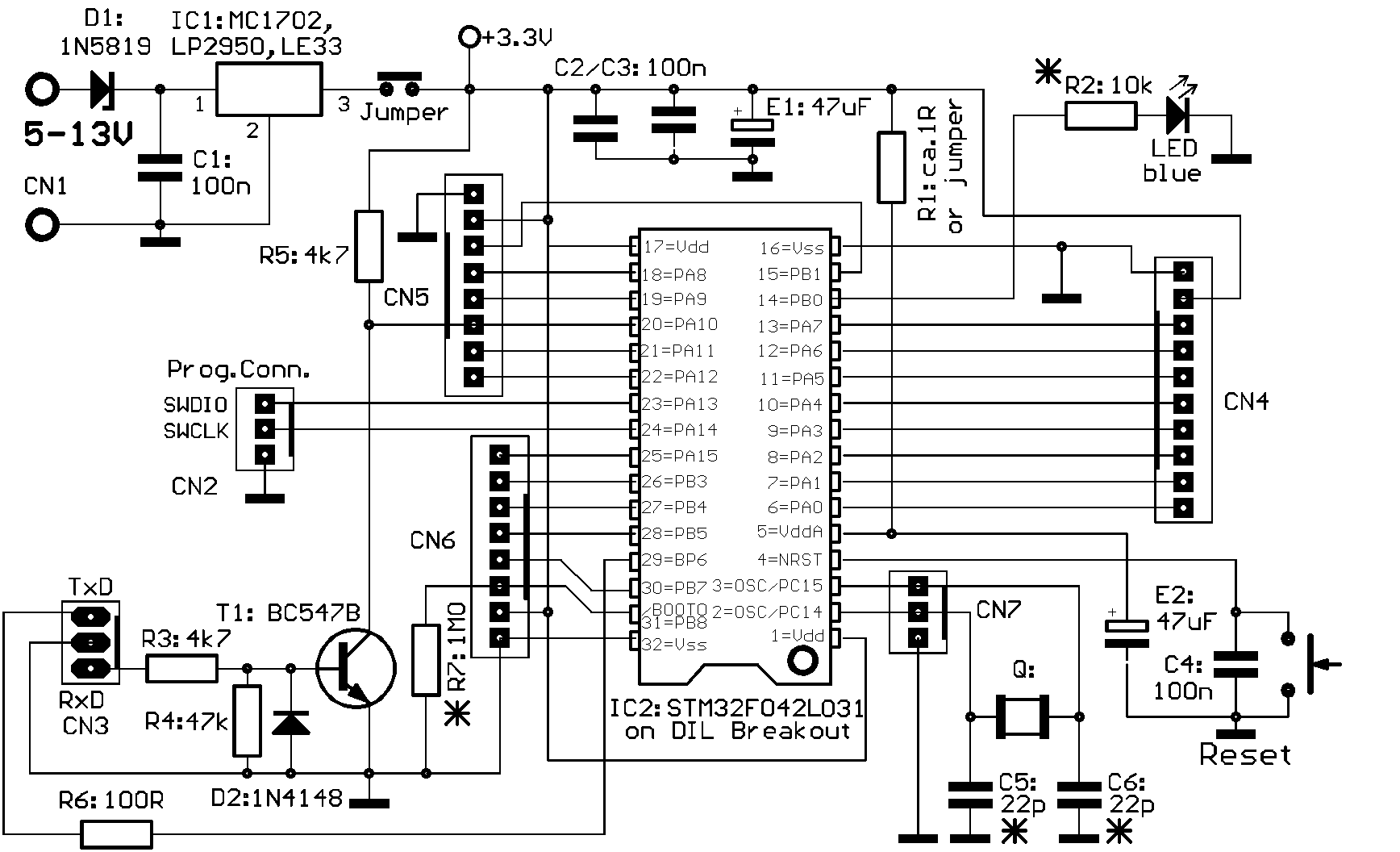
Hardware for STM32G431KB
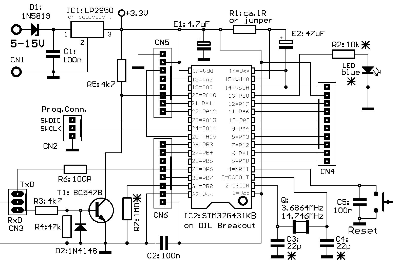
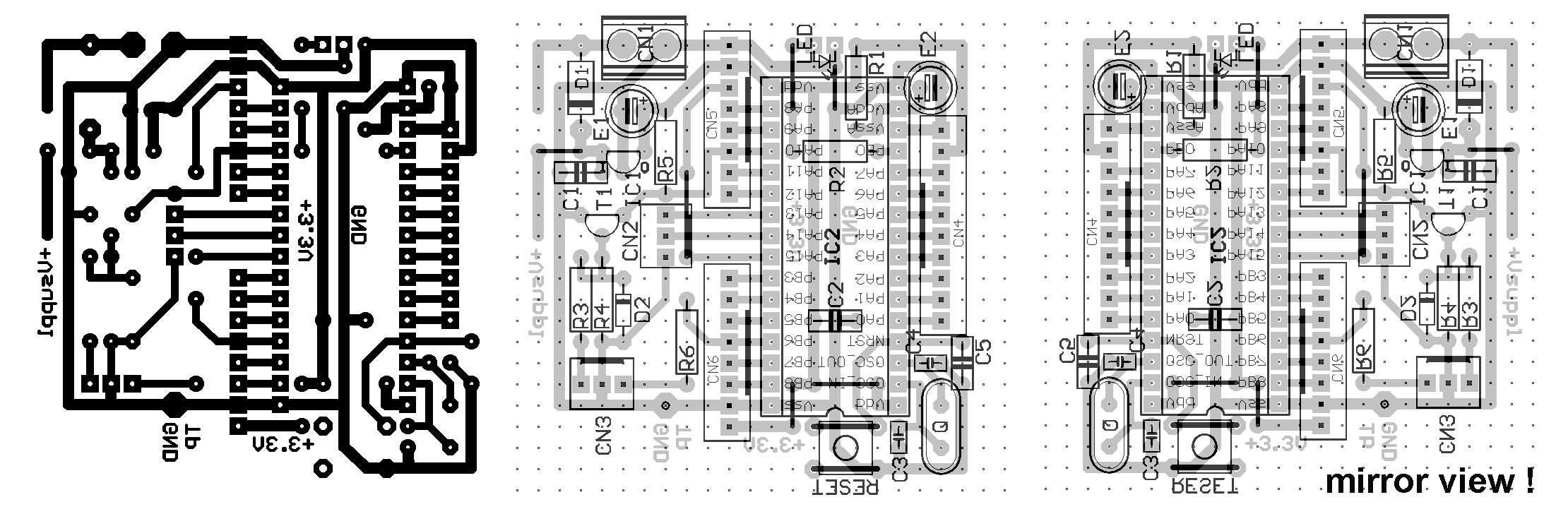
BOTTOM layer as well as component placement view are "from component side", i.e. BOTTOM layer shown mirrored "through the PCB" (as needed for PCB production))
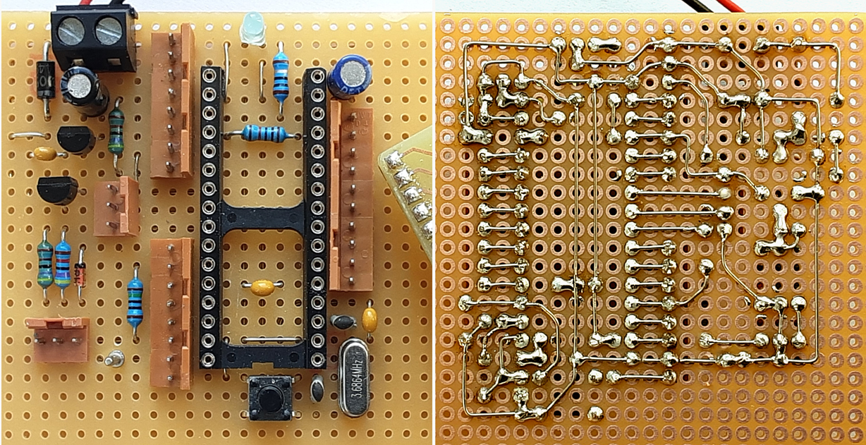
Veroboard layout Original PCB size is 100*75mm. Has been cut off in the picture here for better layout.
Parts marked with * (star):may need individual optimization: R4 depends on VddA current drain. For best filtering, it should be as high as possible, but then low freq ripple might increase. (Vdd – VddA) must be less than 0.3V.
Recommended drill diameters for etched PCB:
resistors, capacitors, diodes, transistor, ICs, jumper wires 0.8mm; LED, connectors 1.0mm;
USB socket: 0.8mm/metal flag 2.0mm or jigsaw slît, CN8 jigsaw slits, fixture holes 3.0mm
Special parts: (cited suppliers are examples where private consumers can buy in Germany)
---STM32G431KB or STM32G441KB: Reichelt, tme.eu, Mouser et.al.
---LQFP to DIL32 breakout board: e.g. Adafruit 1163 (Conrad). It is strongly recommended to scratch off solder resist and mount three small capacitors 100nF between Vdd/Vss and VddA and VssA as near as possible to the microcontroller on the breakout board.
---CN8 (ext.power supply): ROKA brand, Conrad 737992. The minus pins are soldered together at connector bottom side, so only one through hole is used. Other types of power connector may be used, of course.
---LED: blue or white LED recommended, R5 should be about 10k Ohms.
---C3 and C4: most times 22pF are good. If the crystal oscillator does not start, try 33pF or 15pF.
---R1 must be dimensioned project compatible. High value provides good filtering, but may cause ripple if external components are sourced by this voltage. Vdda must not be lower than 0.3V compared with Vdd.
---R7 is usually not necessary and not provided on the PCB. Install it provisionally if you have problems to start ST-Link. See remark at the bottom of this manual.
---RS-232 and programmer connector: source Reichelt PS 25/3G BR or Conrad 741221
---8 pin peripheral connectors: source Reichelt PS 25/8G BR Conrad 741256
---10 pin peripheral connector: source Reichelt PS 25/10G BR Conrad 741264
Recommended drill diameters for etched PCB:
resistors, capacitors, diodes, transistor, ICs, jumper wires 0.8mm; LED, connectors 1.0mm;
Attention: A plastic bar between pins 16 and 17 must be cut off and one jumper wire near pin 32 must be placed before the 32 pin IC socket is mounted.
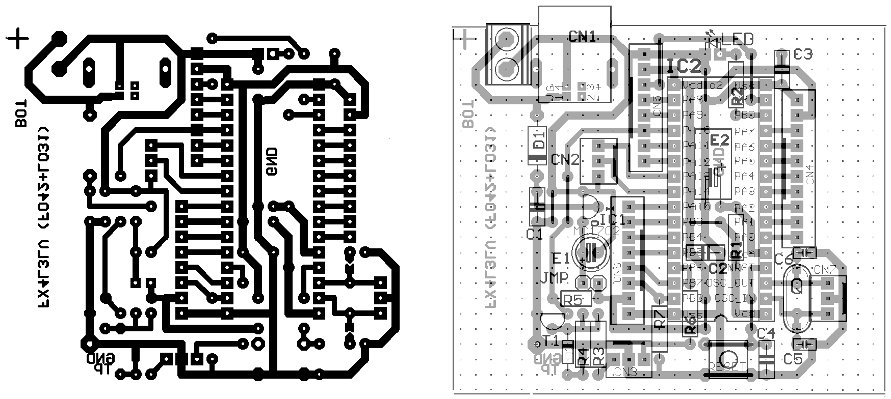
Hardware for STM32F042F6 (20pin TSSOP) (works with STM32F070F6, too)
Hardware for STM32F042K6, STM32L031K6, STM32F030K6 (LQFP32)
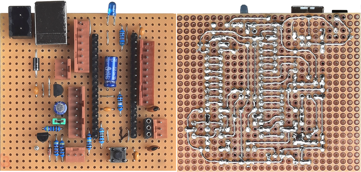
Hints for Veroboard assembly
Care must be taken about pin PB8, which supports the alternative BOOT0 function.
contact: wschemmert@t-online.de, www.midi-and-more.de
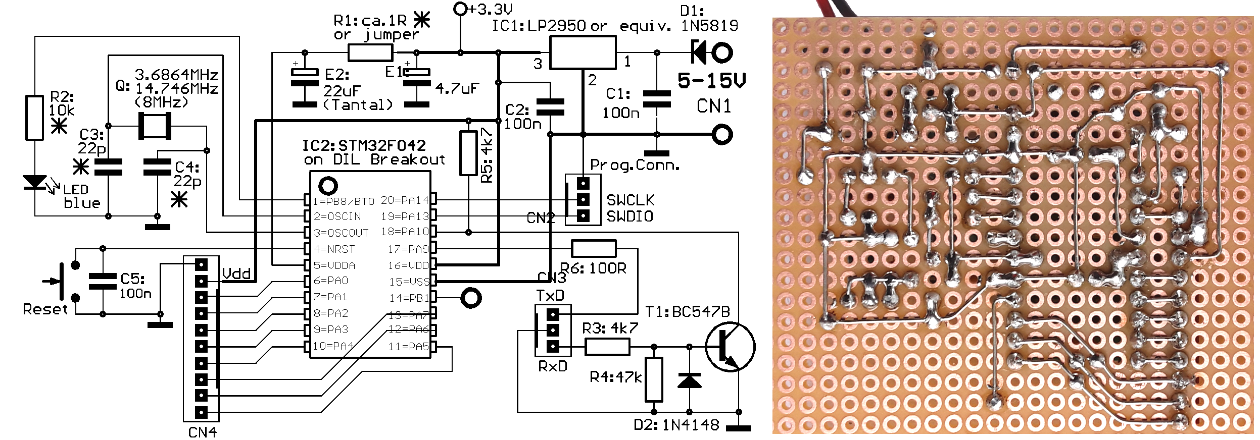
BOTTOM layer as well as component placement view are "from component side", i.e. BOTTOM layer shown mirrored "through the PCB" (as needed for PCB production))
Special parts: (cited suppliers are examples where private consumers can buy in Germany)
STM32F042F6: tme.eu, Mouser et.al., critical to get. Don't confuse with F4 models (only 16kB Flash!)
TSSOP to DIL20 breakout board: e.g. Adafruit 1205 (Conrad) or Reichelt and others.
Other components: see remark above at STM32G431
Download this layout as 1:1 TIF file for PCB production
 Veroboard layout Original PCB size is 100*72mm. Has been cut off in the picture here for better layout.
Special parts: (cited suppliers are examples where private consumers can buy in Germany)
STM32L031K6, STM32F030K6: Reichelt, tme.eu, Mouser. Don't confuse with K4 models (only 16kB Flash!)
---CN1 (ext.power supply): USB-B (only V+,GND connected) or CN1A: 2 pin clamp, 5.12mm raster
---An LP2950 or LE33 voltage regulator can be placed instead of MCP1702 ca 135degree rotated counterClockwise, the rounded side of the case directed towards D1. It's middle pin is GND.
A jumper for supply current measurement is provided at the PCB. Should be shorted by solder when the project is tested and working finally
Other components: see remark above at STM32G431
These processor types have almost the same pinout (differing from STM32G431), but with some essential differences: The STM32L031 has no crystal oscillator included, instead these two pins are provided as additional I/O ports PC14 and PC15. The STM32L031 system clock is derived from the internal MSI RC oscillator with good stability - 1.048 / 4.194 MHz switchable.
For this reason, a flexible PCB layout allows to use the same board for both processor types. The prototype is assembled with a socket to plug the crystal in and with another socket to connect PC14,PC15 + GND with wires. C5 and C6 can easily be un/connected with a drop of solder. But it does not harm when they are connected while STM32L031 I/O is working. Their low-pass cutoff frequency is much beyond the frequencies switched here.
Furthermore, PB8 is not provided at STM32L031 and STM32F030, here it is an exclusive BOOT0 input. Hints for grounding see end of the manual.
It is useful to print a mirrored version of the placement drawing to get a view from bottom=solder side.
The diameter of the wire should be 0.5 or 0.4 mm for easy bending and diagonal wiring between the neighboured copper dots. A set of "adjustment" pliers with small flat tips (or stable tweezers) is recommended for bending and positioning the wires. For 45 degree bendings, a small screw driver pressed on the wire is helpful.
The correct positioning of parts is essential, because there is almost no reserve for alternative positioning. The final solder process is less complicated than it looks. So it is recommended first to place all parts (bigger and typical parts first) and solder them as slightly as possible only to fix them provisionally. Next cut longer wires of fixed components about 1 mm above the Veroboard for later final soldering. At this stage, parts with more than two contacts like connectors should be soldered only at 2 diagonal edge pins. Try to organize the solder sequence in a way that one alreay soldered point is connected with another yet unsoldered, if possible. Points wit 2.5 mm distance are not soldered with a wire, but with a dot of solder instead. If you are connecting points with 3.6 or 5mm distance, becareful not to unsolder the already soldered point due to much heat on the wire.
In some cases jumper wires must be placed before IC sockets. Length and position of all wires (except USB data lines) is uncritical. So if something goes wrong, forgotten or non-placeable wires can be put later directly with isolated wire.
At the STM32F042F6 TSSOP board this is inhibited by the leakage current through the LED (in case of trouble solder 1Meg parallel). At the LQFP boards, R7 is provided.
For the STM32G431 board it is possible too - and recommended - to deactivate this function:
The state ot the BOOT0 pin is only relevant at PowerOn or Reset. After the CPU has booted, PB8 (if implemented) can be used like any I/O port else.
* Right of technical modifications reserved. Provided 'as is' - without any warranty. Any responsibility is excluded.
* This description is for information only. No product specifications are assured in juridical sense.
* Trademarks and product names cited in this text are property of their respective owners.