 back to menue
MIDI / RS-232 Converter
This is a DIY construction manual for an electronic circuit which transforms the physical layer and baudrate of a standard RS-232 signal into MIDI physical layer and baudrate - and vice versa. The RS-232 interface supports 38400, 19200, 9600 and 4800 Baud. The basic mode of operation is bidirectional 1:1 retransmission of every byte. Optionally bytes sent as hex formatted ASCII text to the RS-232 interface are retransmitted in 8 bit format from MIDI OUT. Vice versa, every byte received at MIDI IN is retransmitted then as ASCII text from RS-232. No special drivers or command codes are needed.
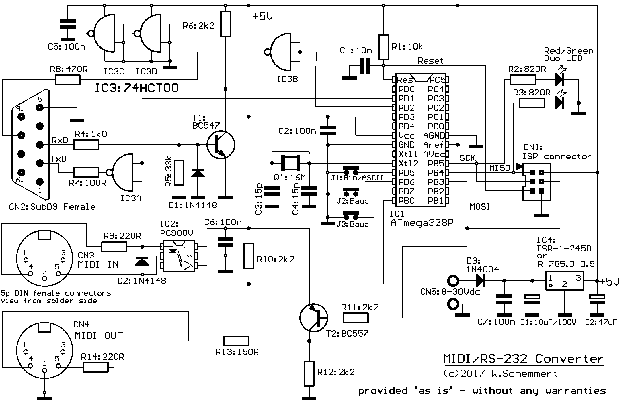
The heart of the circuit is a microcontroller ATmega328P, which provides about 1 kilobyte buffer in each data direction. Alternatively an ATmega88 or ATmega168 may be used, which provide about 400 to 500 bytes buffer in each direction. All features else are the same. Because these microcontrollers are equiped with only one USART, the MIDI interface uses a precise software programmed USART. For best noise suppression every bit of the serial MIDI signal is sampled 7 times and the actual bit level is interpolated. For this reason a relative high clock rate of 16MHz is used.
![]()
An Atmel compatible programming connector is provided on the PCB (CN1).
The data mode is selected by jumper J1 (directed towards the middle of the PCB):
--- default 1:1 binary
--- MIDI<-->ASCII when the jumper is set.
Baud rates are selected by jumpers J2(the middle one) and J3 (directed towards thePCB border):
--- default 38400 (no jumper)
--- 19200 when J2 is placed
--- 9600 when J3 is placed,
--- 4800 when both jumpers are placed.
Instead of jumpers, these pins can be connected with separately mounted toggle switches.
The actual version 5 (as of December 2017) supports CTS handshake for the RS-232 interface. If the control software and the data cable supports CTS handshake too, baud rate 38400 is recommended. No buffer overflow has to be expected then. But the interface is fully compatible be used without CTS handshake, there is simply a higher risk of buffer overflow. Without CTS handshake, baud rate 19200 is recommended for heavy load data transmission from RS-232 to MIDI, while 38400 is recommended for heavy load data transmission from MIDI to RS-232. RTS handshake is not supported, because there is no risk of buffer overflow in the PC at baud rates used here.
![]()
The RS-232 interface is designed as a mixed transistor/HCMOS circuit, which looks simple but works reliably. For proper data input to a remote RS-232 receiver, a negative input voltage during idle or "mark" state is not really necessary. The High/Low threshold of commonly used RS-232 interface chips is about +0.7 to 0.8 Volt. The HCMOS push-pull driver provides a better noise immunity than the transistor driver used in the previous versions.
MIDI OUT is designed with a pull-up transistor, ie. the no-current output level is 0 Volt. So it is impossible to supply other MIDI appliances by this interface.
![]()
The 5 Volt power supply is designed with a 7805 compatible switching regulator, which accepts 8-30Vdc input.
![]()
The dual red/green LED signals presence of power supply and data transfer: In idle state it shines yellow-orange. When bytes are received at CN2 (RS-232), the LED flashes red (green goes off). When bytes are received at MIDI IN, the LED flashes green (red goes off). To get this color scheme, the LED has to be mounted with the flattened side towards the PCB.
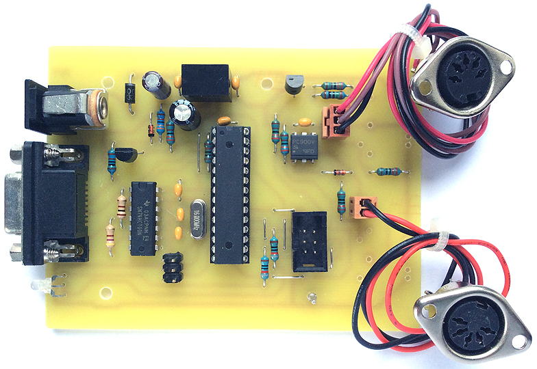
The layout of the PCB is strictly arranged in a 2.54 mm grid and the printed "wires" are put in a way which is well reproducable for manual construction on a veroboard (german: Lochrasterplatine) with copper dots (not stripes). The female subD connector for RS-232 (CN2) and the DIN connectors for MIDI (CN3, CN4) may be soldered directly on the PCB. Alternatively sockets CN3A and CN4A are provided. When no precision mechanical processing is possible, in most cases separate connectors with metal flange are the better solution. This way front panel mounting is easier and looks better.
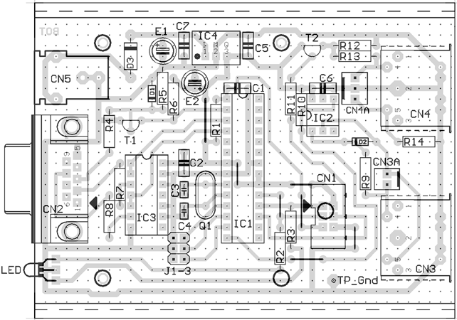
For all holes a 0.8mm drill is recommended, except following parts: CN1,CN2,CN2A,CN3A,CN4A,D3,IC3,jumpers:1.0mm. CN3,CN4:1.3mm. CN5:1.5mm. (CN2 and CN5 do not fit properly into the 2.54 mm grid.)
All resistors are 0.25W types carbon or metal film. All capacitors are preferably multilayer ceramic, 5.08mm raster - except C3 and C4 with 2.54mm raster. Precision tolerance of all parts is uncritical.
Special parts:
CN5 "Roka" brand, Conrad order no.737992.
IC4: TSR-1-2450 (Traco Power), supplied by Conrad and Reichelt. Alternative R-785.0-0.5 (Recom).
LED: L115WEGV, Conrad no.187496. Other types may be used, then R2 and R3 have to be adjusted.
For E1 a low-ESR type is recommended but not necessary.
![]()
|
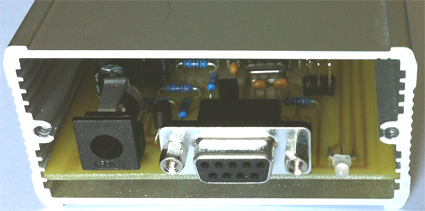
The PCB fits perfectly into an aluminium cabinet model "Fischer Elektronik FRAME",
---Reichelt order code FR 80 42 100 ME.
Alternatively, the PCB fits into a "Euro Box" low cost plastic cabinet:
---Reichelt order "EUROBOX", different colors available
--- Conrad "Donau Elektronik Universal Gehäuse" 523132(grey) and other colors.
Three mounting holes are provided on the PCB.
Downloads:
The subsequently downloadable material is copyrighted (c)2014-17 by Wolfgang Schemmert
Assembly and use of the interface is permitted for free by everybody for any purpose ("freeware")
All information is based on best knowledge, but without any warranty. Any responsibility is excluded.
PCB
Firmware hex code for ATmega328P
Firmware hex code for ATmega168
Firmware hex code for ATmega88
(1:1 TIF format. BOTTOM layer as well as component placement view are "from component side", i.e. BOTTOM layer shown mirrored "through the PCB" (as needed for PCB production))
(rev.5, 29 December 2017 provided 'as is' - without any warranty)
(recommended Fuses configuration: extended 0xFC, high 0xCF, low 0xE7)
(rev.5, 29 December 2017 provided 'as is' - without any warranty)
(recommended Fuses configuration: extended 0xFF, high 0xCC, low 0xE7)
(rev.5, 29 December 2017 provided 'as is' - without any warranty)
(recommended Fuses configuration: extended 0xFF, high 0xCC, low 0xE7)
![]()
* State of information September 2022.
* Right of technical modifications reserved. Provided 'as is' - without any warranty. Any responsibility is excluded.
* This description is for information only, without any warranty. No product specifications are assured in juridical sense.
* Trademarks and product names cited in this text are property of their respective owners.