
CForth with STM32C011J6 (SO8case) on support PCB
It is a little bit funny idea, to create a Forth interpreter for such a tiny processor module with only 4 - or max 5 user available I/O pins. I have built some interesting modules with ATtiny 8 pin processors, so I wanted to check out the newer STM32C011 processor for similar tasks and have my fun.
The biggest problem was to configure a really working Segger Embedded Studio project, the built-in support by Segger is very bad and the STM support (CubeMX) is even worse.
The next challenging problem was to build a solution to switch the STM32C011 system configuration and option bytes for pin4 between NRST and PA1, to get an additional I/O but still be able to make a reset for reprogramming with STM32 Cube Programmer.
These two difficult tasks would have been necessary even for a most simple standalone project with STM32C011.
The CForth interpreter was ported rather easily ported from my CForth Low Power projects, because some of the processors used there have very similar memory resources and the peripheral registers of the different processors are organized very similarily.
Below the line, now I have a comfortable development platform to work on more practical tiny projects, like small stand-alone sensor driven motor applications, battery chargers or alarm beepers.
For this reason the proposed Veroboard compatible PCB layout is made of three parts: left hand standard power connector and manual reset button, middle the processor kernel and user I/O, right hand the terminal interface.
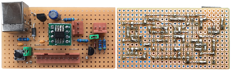
For later practical applications, the middle part may be cut out. This is preempted by two jumpers, which disconnect the CForth necessary add-ons from the processor kernel and application I/O. By Forth commands, the terminal USART Tx can be reprogrammed as additional user I/O, commands can be sent via terminal, but no feedback. At any time the USART Tx can be reativated by CForth command.
The CForth command set for STM32C011 is almost the same as for standard STM32F042:
Detailled CForth Operating Manual (PDF file).
Due to some differences in memory structure and the low-pin restrictions, following differences have to be taken into account:
- Two User Projects are available. Commands:
"0 LOAD" loads a new "Empty" project
"1 LOAD" and "2 LOAD" load project #1 or #2 stored in Flash into SRAM. If this Flash area is still "virgin", an "Empty" project is started.
"0 SAVE" does not save anything, but treats the actual SRAM code as an "Empty" project in work,
"1 SAVE" and "2 SAVE" save the actual SRAM code as project #1 or #2 in Flash.
Differing from CForth with other processors, no separate Flash sector is available to store global parameters like baud rate, decimal or hex number base and which project shall be loaded at system start.
Especially the project to be openend at system start is only stored in Flash of project #1, so project #1 would always be loaded at system start.
To avoid this problem, 2 additional options for SAVE project #1 are implemented:
"10 SAVE" lets CForth start with an "Empty" project, "12 SAVE" lets CForth start with project #2.
Flash content of project #1 is modified with the command sequence e.g. "1 LOAD 12 SAVE" . - Firmware is available for system clock 48Mhz and 3Mhz. Because the internal 48MHz RC HSI oscillator is used in both cases, no hardware change is necessary. Without addtional user peripherals, the 48 MHz version takes ca.5mA supply current, the 3MHz version takes ca.1.5mA. These values are about 1.5 times higher than specified in the data sheet, reason unknown.
CForth parameters for FREQ and PWM are different for 48MHz and 3MHz system clock, see below. - User application pins are addressed as follows:
1=PA1/pin4 (accessibility see below)
2=PA12/pin6
3=PA13/pin7
4=PA14/pin8
5=PA8/pin5. This special command deactivates the USART Tx immediately, pin5 is available as user I/O.
As a side-effect, level changes at PA8 trigger dummy cursor shifts on the terminal window. This is annoying, but usually harmless. For temporary suppression of this side-effect, jumper J2 may be replaced by a switch. - CForth command TXON reactivates the USART TX immediately.
TXON can be sent via terminal even when TX is off, or can be compiled in user code.
User must take care not to get unwanted I/O effects on pin5 then. - further special CForth commands:
NRSET changes the processor configuration of pin4 to NRST, i.e. the reset button resets the processor. This is essential for further reprogramming.
Due to processor internal organisation, a system reset and restart follows immediately. But the new configuration is stored permanently (check with CForth command '?', output line 2).
PA1SET changes the processor configuration of pin4 to PA1, i.e. available as user I/O. Else the same reset action as NRSET. - Cforth commands PWM1, PWM2 and MOT are available simultaneously with following differences:
48MHz clock: 1 FREQ sets freq output to 24kHz. PWM range is 0 to 2000
3MHz clock: 1 FREQ sets freq output to 15kHz. PWM range is only 0 to 200
PWM1 works on pin8/PA14
MOT works together with PWM1 and drives pin6(PA12) and pin7(PA13)
PWM2 works on PA1 and is only available after CForth command PA1SET
SPI: SCK is pin4(PA1), MOSI is pin6(PA12), MISO is pin7(PA13).
PA1 must be activated with command PA1SET
/CS is not implemented directly, must be handled by user, e.g. user I/O#4(pin8/PA14).
Unfortuately SPI uses all user I/O ,except pin5/PA8.
A SPI I/O expansion is available at this website. May be funny. - CForth commands ARRAY, LED, SPEED, SLEEP are not implemented
Downloads:
The subsequently downloadable material is copyrighted (c)2025 by Wolfgang Schemmert.
Assembly of the devices, programming and use of the software is permitted for free by everybody for any purpose ("freeware"). For commercial use, restrictions of third-party software contributors (Segger GmbH, STM) must be respected.
All information is based on best knowledge, but "as is" and without any warranty. Any responsibility is excluded. Use for dangerous, life-threatening and medical applications is forbidden.
Firmware "CForth-C011-48.hex"
SysClock = 48MHz HSI (CPU internal RC oscillator)
(06 December 2025 - first release)
Firmware "CForth-C011-3.hex"
SysClock = 3MHz HSI (CPU internal RC oscillator)
(06 December 2025 - first release)
Source code "CForth-C011-v1.zip"
(state 06 December 2025) This source code is provided as complete "Segger Embedded Studio 8.24" project (ZIP file, 974 kB).
Parts published by Segger GmbH are under license of Segger&|Rowley, parts published by STM are under license of STM, parts programmed by me are provided under GNU GPL3 license.)
This project is programmed directly on register level, no external libraries (except "cmsis" and startup code), no external drivers or HAL are used.
![]()
* State of information December 2025.
* Right of technical modifications reserved. Provided 'as is' - without any warranty. Any responsibility is excluded.
* This description is for information only. No product specifications are assured in juridical sense.
* Trademarks and product names cited in this text are property of their respective owners.